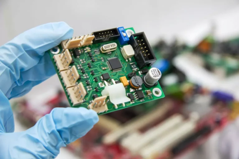
In high-volume printed circuit board production, even minor placement inaccuracies can trigger costly defects such as tombstoning, solder bridges, or complete board failures during reflow.
Automated pick and place machines offer a reliable solution by transforming manual assembly into a repeatable, high-yield process that bridges the gap between prototype and production quality.
These systems, commonly referred to as surface-mount technology (SMT) machines, automate the critical step of positioning components on solder-paste-coated boards.

By combining vacuum nozzles, high-speed motion controls, and machine vision, they achieve sub-50-micron accuracy, surpassing the limits of hand placement.
Desktop models provide hobbyists and small-batch producers with professional capabilities, enabling precise handling of challenging packages such as 0402 passives, QFNs, and fine-pitch BGAs.
In industrial settings, pick and place units manage mixed feeder setups for panels containing hundreds of components, ensuring consistent orientation and centering that withstands thermal stresses during reflow.
The process begins with board alignment, where fiducial markers—small copper targets etched on the PCB—allow cameras to map offsets and compensate for material expansion, stencil misalignment, or panel warp.
Components are sourced from tape-and-reel feeders, trays, or tubes, and vision systems verify part presence, polarity, and orientation before placement.
High-resolution encoders on the X, Y, and Z axes deliver speed without sacrificing precision, while software path optimization reduces head travel to improve cycle time.
Feeder calibration is critical; mismatched tape widths or tension can cause frequent jams that halt the line, making routine maintenance essential.
Industry standards, such as IPC-A-610, define acceptable placement offsets, typically limiting them to 25% of the pad dimension for most parts.
Successful assembly starts upstream with accurate stencil printing, ensuring uniform paste deposition and avoiding bridging or smearing.
Accurate centroid files generated from the design tool map coordinates, rotations, and package dimensions directly into the machine software.
Design for manufacturability considerations include placing at least three non-collinear fiducials, baking moisture-sensitive devices per JEDEC J-STD-033, securing boards with vacuum or mechanical fixturing, and verifying component polarity markings.
For double-sided boards, assembling the bottom side first prevents disturbance of top-side components during flipping.
Operational steps involve homing all axes, loading feeders—starting with taller or larger components to avoid collisions—followed by a dry-run placement on a bare board to validate programming.
Nozzle sizes and Z-heights are adjusted based on component profiles, and initial placements are monitored through vision feedback to correct any detected offsets.
Completed boards are transferred to the reflow oven using anti-static carriers, and advanced features like auto-optimization or multi-head configurations can boost throughput.
Reflow soldering must adhere to J-STD-001 guidelines, including controlled preheat, thermal soak, peak temperature above liquidus for 40–90 seconds, and gradual cooling to prevent defects such as head-in-pillow or voiding.
Post-reflow inspection with automated optical or X-ray systems is standard practice, allowing early detection of hidden faults and reducing shipping failures.
Common challenges include component misalignment caused by poor fiducials or board warp, feeder jams from dust or incorrect tape pitch, tombstoning due to uneven paste or heating, and nozzle pickup failures from dirty nozzles or low vacuum.
Effective solutions involve recalibrating with known-good panels, cleaning feeders and storing them dry, optimizing stencil apertures and reflow profiles, and maintaining clean nozzles with routine isopropyl cleaning.
Best practices for production include organizing components by feeder sequence, performing small validation runs before full panels, meticulously maintaining optics and nozzles, panelizing designs with mouse-bites or V-scores, logging machine data to identify recurring offsets, and prioritizing ESD protection in controlled environments.
Adopting automated pick and place assembly unlocks professional-quality results for both hobbyists and small manufacturers, reducing defects and accelerating development cycles while ensuring reliable, repeatable outcomes.


